This tutorial is aimed at those that wish to know more about the technology behind ADSL and how it is possible to transmit digital data over the telephone line between our home and the exchange.
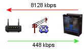
Unlike cable broadband which uses specially laid optical fibre to the premises and forms part of a larger network, ADSL utilises existing telephone cable to bring broadband to the home.
~ How does adsl work - 'on the line'.
| Telephone lines can be used to convey analogue signals and the copper pair has the ability to carry a range of frequencies. DSL makes use of the fact that voice signals for telephone devices are all under 4kHz, and utilises the previously unused higher frequencies to transmit data. |
An adsl splitter is used in the home to separate the telephony and adsl signals and to help ensure that telephony devices don't use any of the frequencies used by ADSL.
- ADSL1 and ADSL2 utilise frequencies up to 1.1 MHz
- ADSL2+ utilises frequencies up to 2.2 MHz
- VDSL2 utilises frequencies up to 17.664 MHz
|
|

|
DSL uses a technology called Frequency Division Multiplexing (FDM) which means it combines multiple frequency signals onto a single carrier wave over a shared medium such as cable, wire or fibre.
Several years ago it was not unusual to hear BT engineers refer to DSLAMs at the exchange as a "Mux" or Multiplexor - DSLAM stands for Digital Subscriber Line Access Multiplexer. |
|

|
 |
|
|
~ What is Modulation?
Because our computers use digital data a MODEM (MOdulator-DEModulator) is needed to code and decode between digital and analogue signals. The method of converting digital data into analogue signals which can be carried over the copper wire is known as Modulation.
|
|
 |
Our modem/routers and the DSLAM at the exchange are the hardware equipment that perform modulation.
There are different methods of modulation, but the common standard used for ADSL is called DMT.
Variations on the basic DMT modulation may be used depending upon the adsl type, but the basic theory remains the same.
| Type |
Standard |
Modulation |
Tech Notes |
| |
|
|
|
| ADSL1 |
G.992.1 |
g.DMT |
DMT standard for adsl1 |
| ADSL2 |
G.992.3 |
g.DMT.bis |
Improved modulation method with flexible framing and optimised use of RS coding gain within the frame structure. Enhanced channel overhead configuration. |
| ADSL2+ |
G.992.5 |
g.DMT.bis+ |
Doubling channels available for use. |
| VDSL2 |
G.993.2 |
|
Extensions: G.INP = G.998.4 Vectoring = G.993.5 |
|
~ What is DMT?
DMT (Discrete Multi Tone) is a method of converting digital data into tones or frequencies that can be carried over telephone wire. Called 'Multi-tone' because it splits the available frequencies into a defined number of smaller sub-channels or tones and 'Discrete' from the mathematical term meaning distinct or separate.
- ADSL1 has 256 sub-channels
- ADSL2 has 256 sub-channels
- ADSL2+ has 512 sub-channels
- VDSL2 (profile 17a) has 4096 sub-channels
DMT deploys many ''virtual modems" which are responsible for the control of each sub-channel.
These virtual modems all work in tandem to carry the data bitstream.
DMT is a modulation method for Frequency Division Multiplexing (FDM) which is when multiple signals are combined and carried over the same medium.
~ How does DMT work?
DMT makes use of the available frequencies that can be transmitted on the telephone line and splits them into 256/512 equal sized frequency bins of 4.3125 kHz each.
Sub-channels (or carrier bins) are where data bits are transmitted to and from our modem. Each sub-channel within a specific frequency range will be responsible for either upstream or downstream data.
- Each carrier bin of 4.3125 kHz is the tone that you may see recorded on some router stats or in DMTtool.
- You may also see sub-channels referred to as carriers, bins or buckets because this is what carries the data bits within each frequency range.
- The full frequency range is split - regardless if you can make use of those frequencies or not.
Not all channels are actually usable for the transmission of data. Some tones are not used such as the pilot tone, whilst some tones are reserved for voice or to prevent overlap of the different signal types.
- Some tones, particularly the higher frequency ones may not be not be in use on longer lines due to the signal strength at that frequency being too weak.
It may help you visualise how DMT works if you imagine this scenario:
Imagine an old 56k modem that worked on the voice band frequency of 0-4kHz.
Now imagine lots of 'virtual' 56k modems each working on their own frequency each giving you 56kbps. As well as splitting the available frequencies, DMT is responsible for 'binding' all these 'virtual modems' together.
ADSL(1&2) has a maximum available 223 downstream subchannels. 223 x 56kbps = 12Mbps.
ADSL2+ doubles the amount of available frequencies (subchannels) and we get 24Mbps.
DMT is the technology which divides the whole bandwidth on the telephone line into lots of sub-channels and then controlling these 'virtual modems' as one together in order to get higher speeds.
~ What frequencies are used?
Below is a chart showing the available frequencies and corresponding frequency tones for various adsl standards.
ADSL
Type |
ADSL
Standard |
Speed
Up to |
Maximum
Frequency |
Upstream
Start |
Upstream
Tones |
Downstream
Start |
Downstream
Tones |
Total
BINs
|
| |
|
|
|
|
|
|
|
|
| ADSL 1 |
G.992.1 |
8 Mbps |
1.1 MHz |
25 kHz |
6-31
|
142.3 kHz |
33-255
|
256
|
| ADSL 2 |
G.992.3
|
12 Mbps |
1.1 MHz |
25 kHz |
6-31
|
142.3 kHz |
33-255
|
256
|
| ADSL 2+ |
G.992.5 |
24 Mbps |
2.2 MHz |
25 kHz |
6-31
|
142.3 kHz |
33-511
|
512
|
| Annex M |
(incr upstream) |
24 Mbps |
2.2 MHz |
25 kHz |
6-56
|
258 khz |
60-511
|
512
|
The calculator on the right will help convert tones into the frequency that it is centered at.
Note:
Care should be taken when looking at the Tone + Frequency BIN numbers from your router. Tone numbering starts at Tone 0, (which is not actually used for the transmission of data). Therefore the 1st bin = Tone 0. The 2nd bin is Tone 1 and centered at 4.3125 kHz etc..
|
|
| DSL Frequency Bins & Tones |
|
|
|
~ VDSL2 Tones in use.
The following tones are in use for VDSL2 FTTC in the UK. The ECI and Huawei cabs have slightly different band plans:
| VDSL2 Band Plans in the UK |
| Tone Set A43/A43c |
Upstream
|
Downstream
|
| Band |
U0
|
U1
|
U2
|
D1
|
D2
|
D3
|
| Tones |
From |
To |
From |
To |
From |
To |
From |
To |
From |
To |
From |
To |
|
Cabinet
|
|
|
|
|
|
|
|
|
|
|
|
|
|
Huawei
|
7 |
32 |
871 |
1205 |
1972 |
2782 |
33 |
859 |
1216 |
1961 |
2793 |
3970 |
|
(BDCM)
|
|
|
|
|
|
|
|
|
|
|
|
|
|
ECI
|
6 |
31 |
882 |
1193 |
1984 |
2770 |
33 |
857 |
1218 |
1959 |
2795 |
4083 |
|
(IFTN)
|
|
|
|
|
|
|
|
|
|
|
|
|
~ Tones which aren't in use.
Certain sub carrier channels are not used. Some of these are laid down in the g.DMT standard, whilst some others may depend upon the DSLAM/MSAN manufacturer and vary slightly.
Common tones not in use are:-
- DC (First Tone). Tone 0.
- Guard Band (Tones 1 to 5 < 25.875 kHz). Tone 1 POTs. Tones 2-5 prevents cross talk between POTs + adsl.
- Guard Band (Tone 32 - 138kHz). Prevents cross talk between upstream and downstream data.
- Nyquist frequency (Final frequency tone)
- Annex_M Stop Band. (Tone 59 - 254kHz). ADSL2+ Annex_M only.
- DSLAM Specific Tones (eg Tones 476 - 499 2053kHz-2156kHz on Be*/02 MSANs only).
- Upstream Pilot Tone for ADSL (Tone 16 - 69kHz)
- Downstream Pilot Tone for ADSL (Tone 64 - 276kHz).
- Adaptive Pilot Carriers. VDSL & some adsl2+ systems select best channel conditions to determine use for pilot tones (eg 105,110 etc). Pilot carriers may change if either the DSLAM or the modem detects noise within the frequency range. The amount of pilot carriers used depends upon the line characteristics.
- Active RFI cancellation. If RFI is detected at a particular tone, then the sub-carrier is taken out of use to prevent noise bleed to neighbouring tones. Some SP's may load profiles for known problematic tones. BTw has been known to use a profile mask on their Huawei MSANs for adsl2+. A typical mask are tones 110, 127, 156,
188,
191,
243,
291.
Your router will also mark any sub-channels where the SNR is too low to carry data as unusable.
~ Tones, carriers, buckets, frequency bins
Generally all of the above terms may be used interchangeably, but to recap and clarify a bit further:
- The whole available frequency band is split into a distinct number of sub-channels.
- With adsl over POTs, the sub-channels form 3 distinct separate channels:
~ Voice
~ Upstream
~ Downstream |
|
|
- Sub channels may also be referred to as carriers, bins or buckets - so called because they are used to carry data bits.
- Each sub-channel has the same amount of bandwidth (4.3125 kHz) but transmits on different frequencies.
- The tone relates to the frequency on which the signal is transmitted.
- Each tone is centered on a specific frequency at which it transmits.
- The amount of data bits that can be carried in the bin can vary depending upon the quality of the signal at the particular frequency range for that particular bin.
|
~ Initialisation and Synchronisation
Synchronisation is communication between your router and the DSLAM at the exchange and sync speed is the rate at which it is agreed that your line can sustain.
On the rate adaptive products before your router is said to be in sync it must go through a process called initialisation to set up the sync speed. Initialisation consists of four key stages:
|
|
- Handshake - Basically saying 'hello can you hear me' and giving details of which technology is to be used (adsl 1, adsl 2 etc) and which protocols are to be used.
Depending upon the technology the number of available subchannels are determined as per the defined standard (G.992.1 G.992.3 etc) The DSLAM will define which sub-channels may be used - for example certain tones are deliberately not used.
- Transceiver Training - Preliminary estimation of loop attenuation, test datastream, reporting of upstream power levels, power level adjustment (cut-back) if needed for spectral masks. Some sub-channels may have masks applied which limit the maximum power level at a particular frequency in order to reduce the risk of cross-talk.
- Channel Analysis - The modem will respond and the condition of each sub-channel is analysed.
Power levels are reported and SNRM and attenuation are calculated. Depending upon the condition (Noise/power level) of each channel, this determines the amount of data bits that can be carried in each channel. See Bit Loading for more information about this stage.
- Exchange - Setting the sync speed. The amount of overall bits that can be carried across all the sub-channels will determine your sync speed. (See Bit Allocation). The dslam will check that the modem can receive data at that speed ok and the router should respond and synchronisation is attained. If not the initialisation process is repeated until sync is achieved.
|
~ Bit Loading
The amount of bits that can be carried per channel depends upon the SNR at that particular frequency, lower SNR levels may need more power to transmit data and since each frequency is subject to an overall power limit, those frequencies are able to carry less bits than a channel with a better SNR.
- The better the SNR at that frequencies in the sub-channel range, then the more bits that can be allocated to that particular carrier bin.
- If the signal is good then 15 bits (maximum) can be allocated to that tone.
- If the SNR is weak/weaker at a particular frequency range, then not as many bits can be carried by the tone.
- Each 3dB of SNR equates to 1 bit (of data),
A minimum of 2 bits per bin is needed for the tone to be usable for ADSL1 (6dB)
ADSL2 and ADSL 2+ support single bit tones (3dB).
- If there's insufficient SNR in the channel, then the carrier bin is marked by the router as unusable.
Bits are encoded as a constellation QAM (Quadrature Amplitude Modulation) which transmit the data by modulating the amplitude of 2 carrier waves. Called Quadrature since the 2 waveforms are out of phase by 90 degrees.
The higher frequencies tend to carry less bits purely because the SNR isn't as good for those channels. Higher frequencies are more likely to be attenuated, therefore the SNR isn't as good and consequentially the carrier bins for those tones cant carry as many data bits.
With rate adaptive dsl, its the SNR of the sub-channels which will determine your sync speed not the frequency of the tone. As long as the SNR at that particular frequency is good then modulation will load x no of bits to the bin regardless if its a high or low frequency.
Lines which are more attenuated will see SNR decrease more rapidly at the higher frequencies hence less bit allocation overall and a lower sync speed.
~ Bit Allocation
Each tone is capable of carrying up to 15 bits regardless of the frequency at which it is transmitted. The amount of bits actually allocated to the bin purely depends on the SNR for that particular bin.
As an example:
Say you have a bin at tone 192 @ 828kHz that has an SNR of say 50dB, then that's more than enough SNR to allocate the full 15 bits to the carrier.
Now say at tone 194 @ 836kHz, there's some noise broadcasting at that same frequency which takes the SNR down to 25dB, then only 5 bits may be able to be encoded on that channel.
But frequency bands slightly further up may be fine and back up at 50dB SNR so 15 data bits are encoded on that tone.
Bit Allocation is not actually quite as straight forward as in the above example and there's more to it during the sync negotiation period which has to cover an allowance for errors as defined by the Bit Error Rate (BER) and involves a fairly complicated process called Quadrature Amplitude Modulation (QAM) which is beyond the scope of this tutorial, and this is what determines the final sync speed. Somewhere in that process is the required overhead for Interleaving and/or more correctly Error Correction, and of course the Target SNR which sets some sort of base line, but...
- The QAM rate is said to be 4,000 symbols per second, therefore each 3dB of SNR available in the sub channel over the base line will give approx 4kbps of sync speed, subject to a maximum of 60kbps (15 x 4kbps) per carrier.
- Sync rate depends on the number of bits loaded. With adsl each 3db of SNR is worth anywhere between 400 to 1200kbps of speed.
- VDSL uses higher frequencies and has more available tones for loading. A rough guide is :
~ Sync speeds of around 20Mbps - each 3dB is worth 3Mbps
~ Sync speeds of around 40Mbps - each 3dB is worth 6Mbps
~ Sync speeds of 60Mbps or more - each 3dB is worth 11Mbps.
~ Bit Allocation Table
Once a line has sync'd a Bit Allocation Table (BAT) is defined which is what specifies how many bits are used/can be used within the sub-carrier channel.
All modem routers will maintain a Bit Allocation Table and some routers allow you to view the Bit Allocation Table which may be useful for diagnostics.
~ Bit Swapping
| Bit Swapping is a way of keeping the line more stable by constantly monitoring the frequency bins (carriers) in use and reusing them if possible. |
The bit swap process enables the connection to either change the number of bits assigned to each individual subchannel or if necessary increase the power level (gain) whilst still maintaining the data flow.
If after sync the SNR within a specific tone falls too low to transmit x no of bits, then bit swapping allows any 'spare' in other sub channels to be used, whilst still maintaining the same number of total bits in the Bit Allocation Table.
There's a minimum amount of bits in a channel.. and if the bits fall too low (say if you had a quick noise burst at a certain frequency) then the router could mark that channel as unusable which may cause the line to lose connection. A carrier bin needs a minimum of 2 bits = 6dB of SNR to be usable for adsl1 or 3dB for adsl2/2+.
With bit swapping the router can swap the bits around and redistribute the bits to other channels by using any spare SNR at other frequencies or increasing the gain.
Without bit-swapping, your connection would lose sync every time there was a noise burst that meant any sub-channel wasn't able to transmit its allocated number of bits.
|
|
 |
~ Bit Error Rate (BER)
The Bit Error Rate is calculated as the percentage of transmitted bits which contain errors. Many routers have the ability to conduct a Bit Error Rate Test (BERT). For the duration of the test the router will count the number of bits transmitted which is divided by the number of erroneous bits.
The result may be displayed as a figure with 10 to a negative power for example 10–7 which is 0.0000001 or 1e-7.
To put it simply a BER of 10–6 is one errored bit in every 1,000,000 bits transmitted.
The standard allowance for Bit Error Rate in adsl is a BER of 10–7. The SNR margin is calculated as SNR minus an allowance for a 10–7 BER.
During a BER test, if the router is measuring CRCs in the FAST path bit stream , then 1 CRC is the equivalent of 20 bit errors and 50 bits for interleaved path.
~ Bit Allocation and Power Cut Back
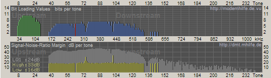
Below is an example of a healthy line showing the Bit Allocation Table and SNR statistics from a router with the aid of DMT tool.
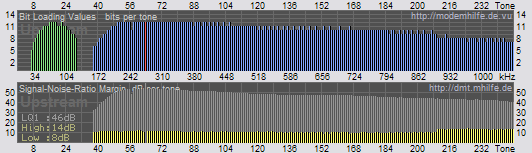
- Notice how the shape of the Bit Allocation (blue lines) correlate to the SNR (grey lines) in the lower table. The yellow lines show the SNR Margin.
- Also note the smooth curves at on the upstream causing a inverted 'U' and also at the beginning of the downstream. This is likely due to spectral masks applied at the DSLAM which ensures that power levels are cut back to reduce the likely hood of cross-talk on those frequencies.
- Another interesting observation about this particular line, is that power levels have been cut back across all bins (From a max of 20dBm down to 11.9dBm).
Cutting back on power reduces the signal strength, which in turn reduces the SNR. The above line is very good with little noise, therefore without this cut back the above line would likely 'drown out' neighbouring lines at the DSLAM causing cross-talk for other lines.
Note also how it can easily sync at the full 8128 kbps without having to assign the full 15 bits to any one particular tone.
~ Bit Allocation Table and Low SNR
Below is an example of a line that is more susceptible to noise.
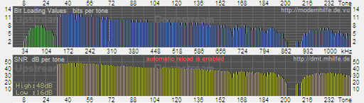
- Despite having an attenuation of 30dB, the line was slightly under-performing at around 5.8 mbps.
- Note the gaps and decline in SNR (yellow lines) at around tones 203 - 211.
- This is indicative of additional noise/interference in the frequency ranges 875kHz - 914kHz
- The decline in SNR at these frequencies has had a corresponding effect on the bit loading so that either side only 2 bits per bin have been able to load.
- At the worst points the SNR was so low, that the router has not been able to use tones 203-207 & 210-211 at all.
- The over-all effect of less bits loaded is a lower than anticipated sync speed.
After internal re-wiring and changing filters noise was reduced on the offending channels and the line is now able to sync at the full 8Mb.
~ Bit Allocation and Long Lines
Below is a graph showing the bit loading on a long (59dB) line. Although the line is quite long it is able to sync at speeds up to around 2Mbps
- Long lines are naturally higher attenuated therefore SNR across all channels is lower.
- Lower SNR means less bits can be loaded per bin = lower sync speed
- Notice natural tail off of SNR at the higher frequencies
- Note where the SNR + SNR Margin at Tones 132-137 is too low to allocate any bits
- A few tones at 140+ have just sufficient SNR (grey lines) to allocate 2 bits (blue lines).
What is interesting about the above line is notice the corresponding high peak in the SNR Margin, with the lower bit loading at tone 74 and tone 101. This particular line had been up for a couple of days when the graph was loaded. The yellow peaks indicate that that if a resync was performed 'now' then those bins would likely load more bits to gain a higher sync speed. This could be typical of a line that each evening receives a small amount of background noise' on those channels. On this particular line, the amount of additional bits available probably wont make that much difference, but the graph is a good indication what to look for and shows how lines can vary over the course of the day.
~ Seamless Rate Adaption (SRA)
Seamless Rate Adaption (SRA) is a method which dynamically adapts your line rate /sync speed on the fly depending upon the current condition of your line without having to perform a full retrain or resync.
Normally when your SNR Margin falls too low for your router to 'hear' the signal from the exchange your connection will drop and you lose synchronisation with the exchange. The router then has to re-negotiate a lower sync speed causing a small period of time without connectivity.
With SRA, line conditions are constantly monitored and any increases/decreases in SNR result in an increase/decrease in the line connection speed without having to go through the initialisation process.
Line speed will always be at the highest possible rate depending upon your set target SNR, which is particularly useful if you have had a low synch and line conditions later improve, as SRA will ensure that your line speed will increase in line with the better conditions.
Both the router and DSLAM need to be able to support SRA.
Presently the only ISP in the UK that supports SRA is UKOnline on their adsl 2+ LLU exchanges.
|